Project No. 24: Creating a Smart Automatic Zebra Crossing
1. Introduction:
Introducing the Smart Zebra Crossing project—a modern solution designed
to make pedestrian crossings safer and more efficient. Our innovative system
utilizes advanced technology to improve the flow of both vehicles and
pedestrians.
Traditional zebra crossings often face challenges, leading to congestion
and potential safety risks. Our project aims to overcome these issues by
incorporating intelligent features. With the help of servo motors, we control
separate gates for vehicles and pedestrians. This ensures smooth traffic flow
while prioritizing pedestrian safety.
To enhance safety further, we have included a buzzer component. When the
pedestrian gate is about to open, the buzzer emits a warning sound. This alerts
pedestrians to the gate's movement, providing an additional layer of caution
during crossing. In
addition to the buzzer, we have integrated a signal light system. This system
uses visual signals, such as red and green lights or symbols, to indicate
when it is safe for pedestrians to cross. Synchronizing the signal lights with
the gate operation ensures clear guidance for pedestrians.
Introducing the Smart Zebra Crossing project—a modern solution designed
to make pedestrian crossings safer and more efficient. Our innovative system
utilizes advanced technology to improve the flow of both vehicles and
pedestrians.
Traditional zebra crossings often face challenges, leading to congestion
and potential safety risks. Our project aims to overcome these issues by
incorporating intelligent features. With the help of servo motors, we control
separate gates for vehicles and pedestrians. This ensures smooth traffic flow
while prioritizing pedestrian safety.
To enhance safety further, we have included a buzzer component. When the
pedestrian gate is about to open, the buzzer emits a warning sound. This alerts
pedestrians to the gate's movement, providing an additional layer of caution
during crossing.
In addition to the buzzer, we have integrated a signal light system. This system uses visual signals, such as red and green lights or symbols, to indicate when it is safe for pedestrians to cross. Synchronizing the signal lights with the gate operation ensures clear guidance for pedestrians.
2. Working:
Step1: Initialization:The project starts with initializing the
microcontroller and setting up the necessary connections for the servo motors,
signal lights, and buzzer.

Step2: Signal Light Monitoring:The microcontroller constantly monitors the
state of the signal lights to determine the current traffic condition. This can
be achieved by interfacing with the existing traffic light system or using
sensors to detect the color of the lights.


When the pedestrian signal turns green,
indicating that it is safe for pedestrians to cross, the microcontroller sends
a command to the servo motor controlling the pedestrian gate. The servo motor
rotates to open the gate, allowing pedestrians to enter the zebra crossing
area.
Step3: Buzzer Activation: As the pedestrian gate opens, the
microcontroller activates the buzzer to generate an audible alert, indicating
to pedestrians that the crossing is about to open. This alerts pedestrians to
be prepared to cross safely.
Step4: Crossing Period: The pedestrian gate remains open for a
predefined period, allowing pedestrians to cross the road. During this time,
the buzzer may continue to provide intermittent alerts, reminding pedestrians
to proceed promptly and attentively.
Step5: Vehicles Gate control: After the designated crossing period elapses, the
microcontroller commands the servo motor controlling the pedestrian gate to
close it, ensuring that no new pedestrians enter the crossing.
Simultaneously, the
microcontroller continues monitoring the state of the signal lights for
vehicles. When the vehicle signal turns green, indicating that vehicles have
the right of way, the microcontroller commands the servo motor controlling the
vehicle gate to open it, allowing vehicles to pass through the zebra crossing
area.
The vehicle gate remains open
for a specific duration, providing sufficient time for vehicles to cross the
crossing safely.
Step6: Gate Closure: After the vehicle crossing period concludes, the
microcontroller commands the servo motor controlling the vehicle gate to close
it, ensuring the safety of pedestrians and preventing any vehicles from
entering the zebra crossing area.
Step6: Looping:The system continues to monitor the signal
lights and repeats the process from Step 3, allowing pedestrians and vehicles
to cross the zebra crossing smoothly and safely as per the signal light
timings.
Step1: Initialization:
The project starts with initializing the
microcontroller and setting up the necessary connections for the servo motors,
signal lights, and buzzer.

Step2: Signal Light Monitoring:
The microcontroller constantly monitors the
state of the signal lights to determine the current traffic condition. This can
be achieved by interfacing with the existing traffic light system or using
sensors to detect the color of the lights.


When the pedestrian signal turns green,
indicating that it is safe for pedestrians to cross, the microcontroller sends
a command to the servo motor controlling the pedestrian gate. The servo motor
rotates to open the gate, allowing pedestrians to enter the zebra crossing
area.
Step3: Buzzer Activation:
As the pedestrian gate opens, the
microcontroller activates the buzzer to generate an audible alert, indicating
to pedestrians that the crossing is about to open. This alerts pedestrians to
be prepared to cross safely.
Step4: Crossing Period:
The pedestrian gate remains open for a
predefined period, allowing pedestrians to cross the road. During this time,
the buzzer may continue to provide intermittent alerts, reminding pedestrians
to proceed promptly and attentively.
Step5: Vehicles Gate control:
After the designated crossing period elapses, the
microcontroller commands the servo motor controlling the pedestrian gate to
close it, ensuring that no new pedestrians enter the crossing.
Simultaneously, the
microcontroller continues monitoring the state of the signal lights for
vehicles. When the vehicle signal turns green, indicating that vehicles have
the right of way, the microcontroller commands the servo motor controlling the
vehicle gate to open it, allowing vehicles to pass through the zebra crossing
area.
The vehicle gate remains open
for a specific duration, providing sufficient time for vehicles to cross the
crossing safely.
Step6: Gate Closure:
After the vehicle crossing period concludes, the
microcontroller commands the servo motor controlling the vehicle gate to close
it, ensuring the safety of pedestrians and preventing any vehicles from
entering the zebra crossing area.
Step6: Looping:
The system continues to monitor the signal
lights and repeats the process from Step 3, allowing pedestrians and vehicles
to cross the zebra crossing smoothly and safely as per the signal light
timings.
3. What is IR sensor?
An IR sensor, also known as an infrared sensor, is a device that detects and measures infrared radiation in its surroundings. Infrared radiation is an electromagnetic radiation with longer wavelengths than visible light but shorter wavelengths than radio waves.
IR sensors consist of an emitter and a receiver. The emitter emits infrared radiation, and the receiver detects the reflected or emitted radiation. When an object is present in the sensor's field of view, it reflects or emits infrared radiation, which is then detected by the receiver. The sensor analyzes the received signals to determine the presence, proximity, or movement of objects.
4. Things that you will get with models:
1. Detailed Model
2. Well soldered circuits
3. PPT4. similar model as above
1. Detailed Model
2. Well soldered circuits
3. PPT
4. similar model as above
5. Project price:
You can buy this project at price 1500 Rs.
You can also customize your project according to your requirement as below:
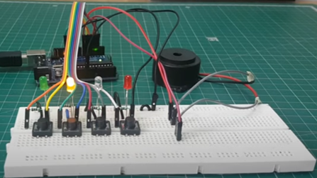
The price of this projects depend on the component used in the model, for example in the above model the component used is:
1. Arduino UNO2. 2 x Servo Motor3. Battery for power supply.4. LED and Resistor5. Buzzer6. Connecting wire7. Other small components
There are some other optional component available that you can remove or add it to the model according to your need, so the price of the project will decrease or increase according to price of component according to price of component and coding.
In summery, you can tell us what functionalities and components that you want to add or remove from the model, so the price will change accordingly. If you have any question related to this project then contact me: click here Basically you will get all this things that required to present this project in front of your external, teacher, for practical use at your home or to show off in front of your friends 😉😉,so if you want to buy this project then fill this google form: https://docs.google.com/forms/d/e/1FAIpQLSfDQvyFqN1iDLOFhGNB0KK_nEW1rZujUEdmvNNQNazXK4tAZA/viewform?usp=sf_link
You can buy this project at price 1500 Rs.
You can also customize your project according to your requirement as below:
The price of this projects depend on the component used in the model, for example in the above model the component used is:
2. 2 x Servo Motor
3. Battery for power supply.
4. LED and Resistor
5. Buzzer
6. Connecting wire
7. Other small components
There are some other optional component available that you can remove or add it to the model according to your need, so the price of the project will decrease or increase according to price of component according to price of component and coding.
In summery, you can tell us what functionalities and components that you want to add or remove from the model, so the price will change accordingly. If you have any question related to this project then contact me: click here
Basically you will get all this things that required to present this project in front of your external, teacher, for practical use at your home or to show off in front of your friends 😉😉,so if you want to buy this project then fill this google form: https://docs.google.com/forms/d/e/1FAIpQLSfDQvyFqN1iDLOFhGNB0KK_nEW1rZujUEdmvNNQNazXK4tAZA/viewform?usp=sf_link
Note: The image shown is a conceptual representation and may not accurately reflect the final design or features of the actual model. The actual model will be developed based on extensive research, engineering, and design processes to ensure optimal performance and user experience.
Feel free to contact me I am always here for you
About Us: click hereContact Detail: click hereFor delivery detail: click here Telegram: https://t.me/arduinoproject1
Note: The image shown is a conceptual representation and may not accurately reflect the final design or features of the actual model. The actual model will be developed based on extensive research, engineering, and design processes to ensure optimal performance and user experience.
Feel free to contact me I am always here for you
About Us: click here
Contact Detail: click here
For delivery detail: click here
Telegram: https://t.me/arduinoproject1

Comments
Post a Comment